Wave Rover: Setup Guide and Troubleshooting Tips
After a long wait, my Wave Rover, a robust 4WD full-metal body mobile robot chassis, and the RoArm-M2-S, a 4DOF smart robotic arm designed for innovative applications, have finally arrived. Along with these, I received three 18650 lithium batteries (which are not included in the base package) for powering the setup.
Initial Preparation
To begin, I carefully opened the Wave Rover chassis by loosening the four screws on the bottom with an allen key, ensuring not to pull any wires accidentally.
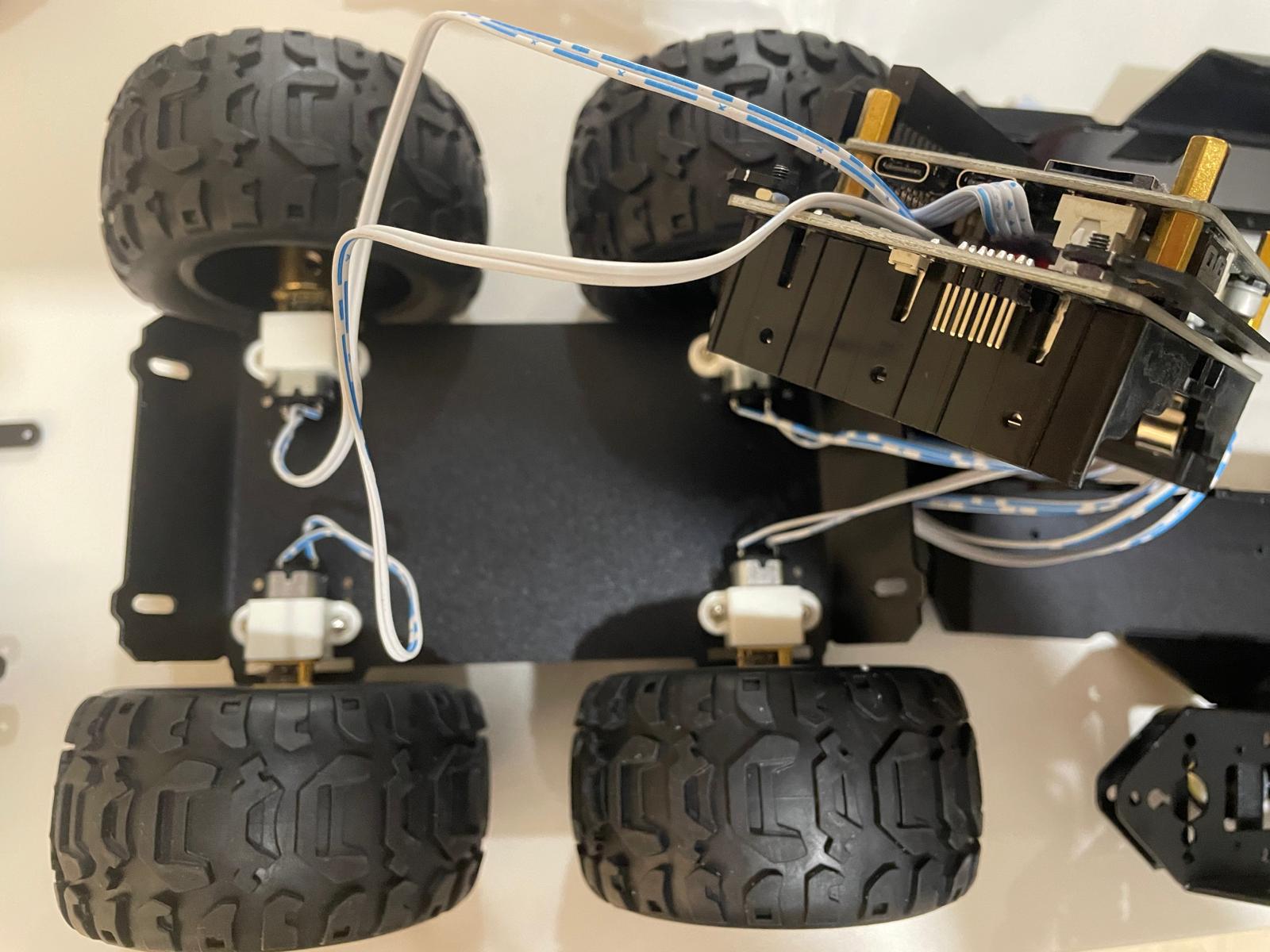
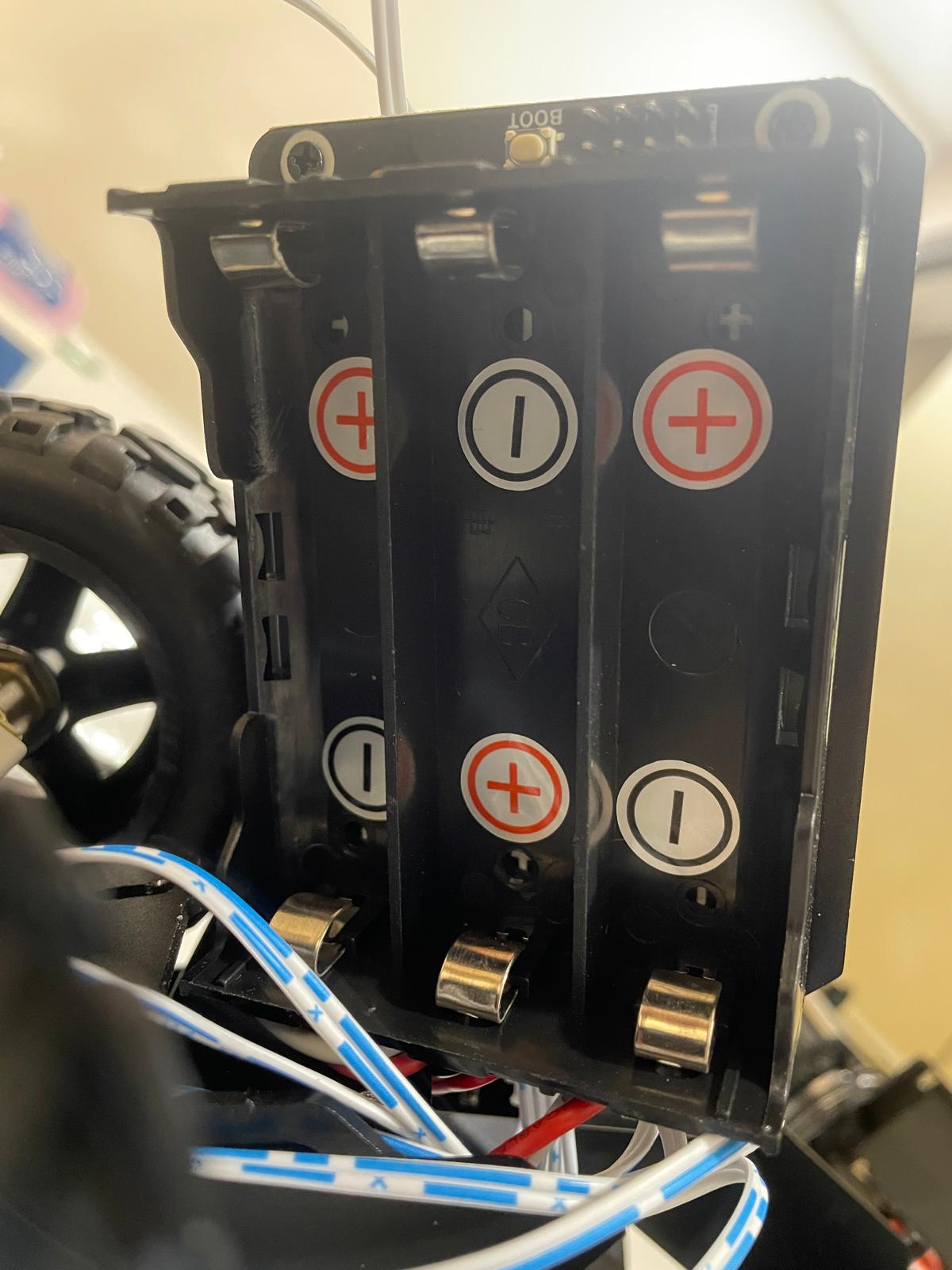
Next, I installed the three 18650 batteries into the compartment. It’s essential to ensure that the battery polarity is correct to avoid damaging the electronics.
After assembling the RoArm-M2-S onto the chassis, this was my initial setup:
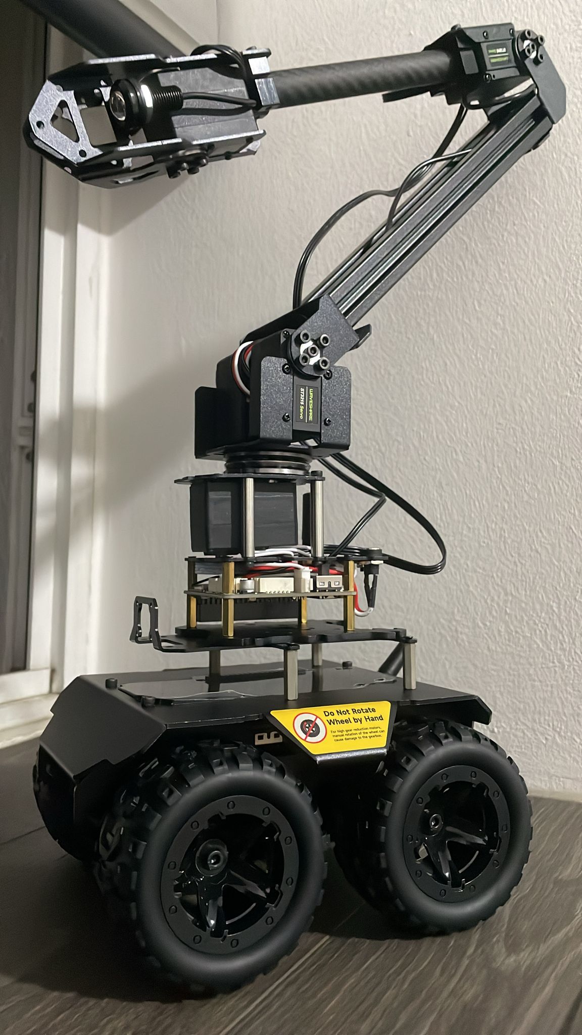
However, due to the high center of gravity (CG), if the Wave Rover moves too fast or experiences sudden jerks, the robotic arm tends to topple over easily. As a solution, I removed the arm and decided to focus on testing the Wave Rover itself. In the future, I plan to either design a larger, more stable base with counterweights or 3D print a custom base. Another approach might be to limit the acceleration and deceleration of the rover to stabilize the arm during movement.
Getting Started with Wave Rover
Since the Wave Rover supports charging while in use, after powering it on, I connected to its Wi-Fi network named UGV (default password: 12345678). The control panel can be accessed by navigating to http://192.168.4.1 in a web browser.
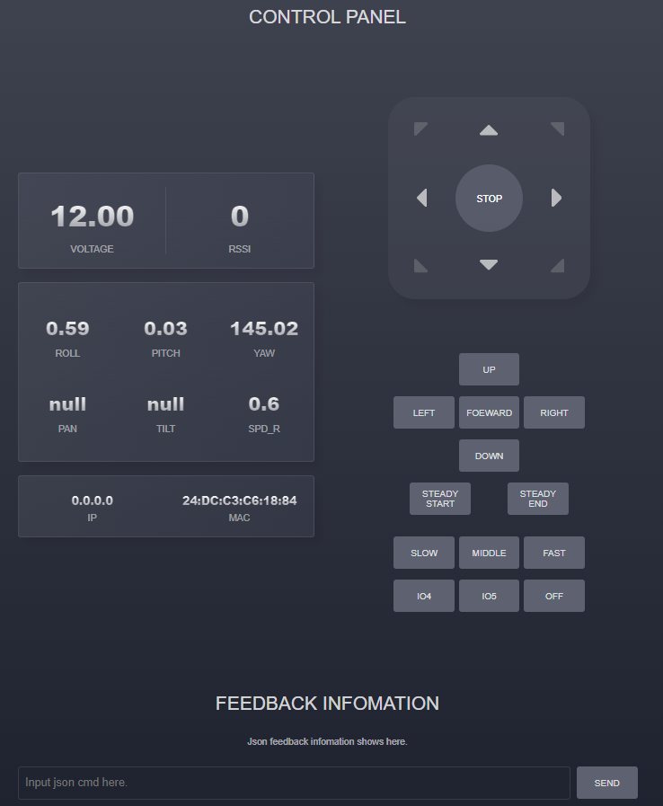
Once connected, I could control the rover using the on-screen buttons or my keyboard’s arrow keys.
Issue JSON Commands via the Web Interface
The rover’s control system supports various commands in JSON format. For example, the left and right wheel speeds (CMD_SPEED_CTRL) can be controlled within a range from -0.5 to 0.5, where positive values move the rover forward and negative values move it backward. Since the motors don’t have encoders, a value of 0.5 represents 100% PWM.
{"T":1,"L":0.1,"R":0.1}
There are several other commands available in the web application. To connect the rover to another Wi-Fi network, use the following command:
{"T":404,"ap_ssid":"UGV","ap_password":"12345678","sta_ssid":"your_ssid","sta_password":"password"}
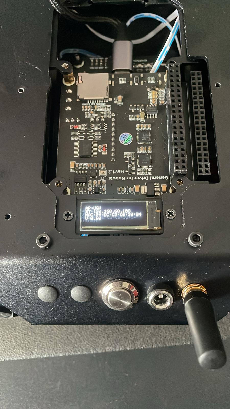
After this, the rover can be accessed via the new IP address, which is displayed on its OLED screen.
Controlling Wave Rover via Python
For those who prefer scripting, the following Python script can issue HTTP-based JSON commands to the rover:
import requests
import argparse


def main():
    parser = argparse.ArgumentParser(description='Http JSON Communication')
    parser.add_argument('ip', type=str, help='IP address: 192.168.10.104')

    args = parser.parse_args()

    ip_addr = args.ip

    try:
        while True:
            command = input("input your json cmd: ")
            url = "http://" + ip_addr + "/js?json=" + command
            response = requests.get(url)
            content = response.text
            print(content)
    except KeyboardInterrupt:
        pass


if __name__ == "__main__":
    main()
To run the script, simply execute the following command, replacing the IP with your rover’s IP:
# Enter your IP address displayed in the OLED screen
python http_simple_ctrl.py 192.168.68.108
Here are a few commands you can try:
// To move backwards
{"T":1,"L":-0.1,"R":-0.1}

// To show test in the OLED screen
{"T":3,"lineNum":0,"Text":"putYourTextHere"}

// To reset back to the initial OLED display
{"T":-3}
Programming the Driver Board for the Wave Rover
For more advanced control, follow the official guide on How to install Arduino IDE and download the Arduino IDE.
Installing the ESP32 Plug-in
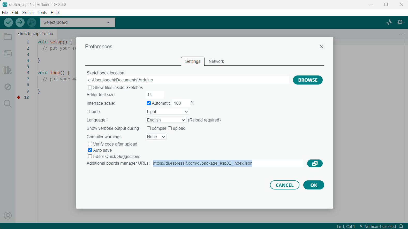
- Start the Arduino IDE and navigate to File > Preferences. In the “Additional Boards Manager URLs” field, enter the following URL: https://dl.espressif.com/dl/package_esp32_index.json:
-
Download the ESP32 development package and extract it to C:\Users\username\AppData\Local\Arduino15.
-
Next, download the necessary libraries and place them in the libraries folder under C:\Users\username\Documents\Arduino.
Uploading the Wave Rover Demo
-
Download the Wave Rover Open-source Demo, unzip it, and open the WAVE_ROVER_V0.9.ino file in the Arduino IDE.
-
Connect the Wave Rover driver board to your computer via USB-C:
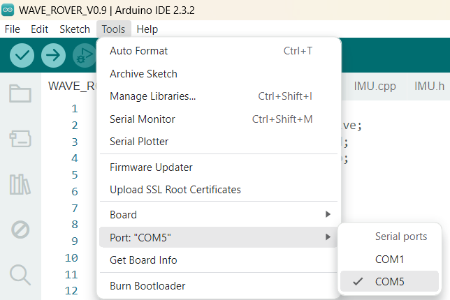
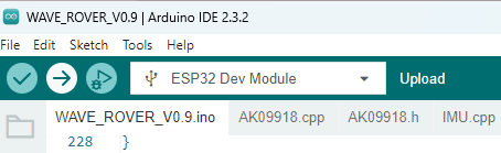
- Select the appropriate COM port (e.g., COM6), which should appear once the board is connected:
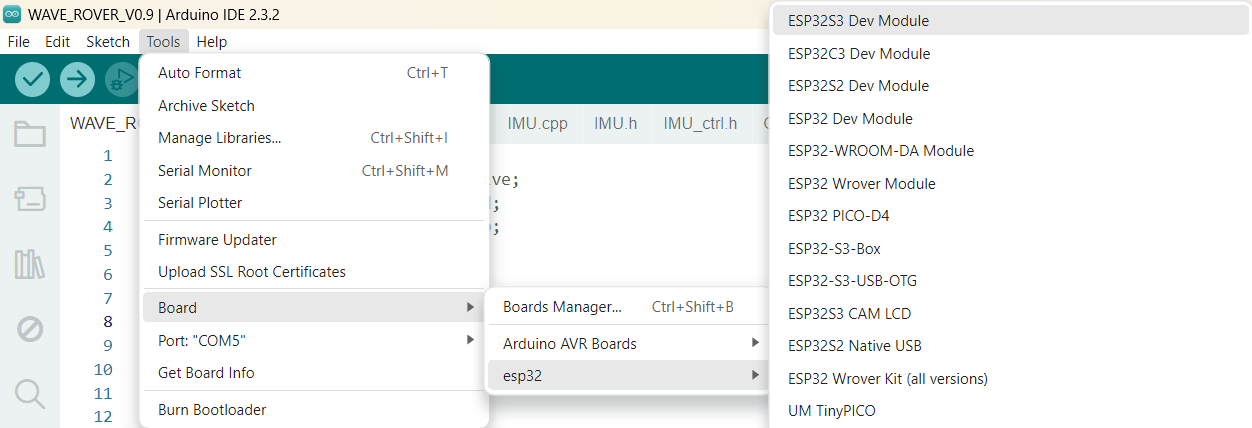
- Under Tools > Board > esp, select the ESP32 Dev Module:
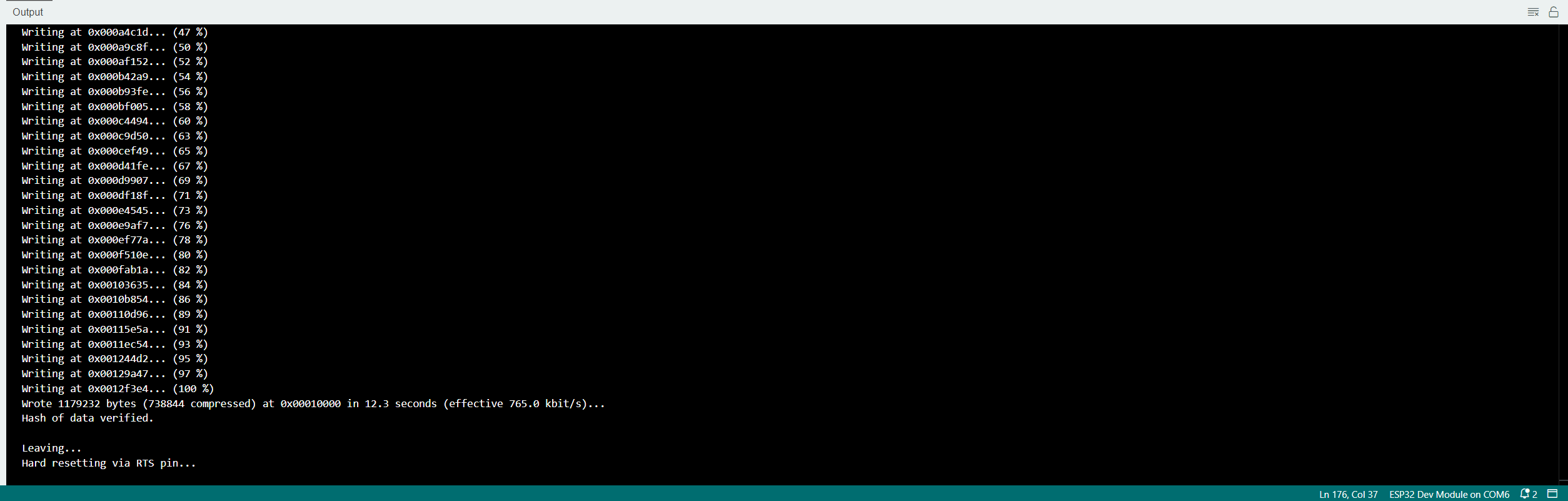
- Finally, upload the demo to the rover.
Once uploaded, the setup() function is executed once for initialization, while the loop() function runs continuously to handle real-time interactions. However, after rebooting, I noticed that the rover did not respond to any web server commands, which I’ll address in the reset section.
Motor Control Demo (Without Encoder)
Below is the content of the nospeedget.ino file. I had to comment out ledcSetup and ledcAttachPin to avoid compilation errors:
const uint16_t PWMA = 25;
const uint16_t AIN2 = 17;
const uint16_t AIN1 = 21;
const uint16_t BIN1 = 22;
const uint16_t BIN2 = 23;
const uint16_t PWMB = 26;

const uint16_t ANALOG_WRITE_BITS = 8;

int freq = 100000;
int channel_A = 0;
int channel_B = 1;
int resolution = ANALOG_WRITE_BITS;

void initMotors(){
  pinMode(AIN1, OUTPUT);
  pinMode(AIN2, OUTPUT);
  pinMode(PWMA, OUTPUT);
  pinMode(BIN1, OUTPUT);
  pinMode(BIN2, OUTPUT);
  pinMode(PWMB, OUTPUT);

  //ledcSetup(channel_A, freq, resolution);
  //ledcAttachPin(PWMA, channel_A);

  //ledcSetup(channel_B, freq, resolution);
  //ledcAttachPin(PWMB, channel_B);
}

void forwardA(uint16_t pwm){
  digitalWrite(AIN1, LOW);
  digitalWrite(AIN2, HIGH);
  ledcWrite(channel_A, pwm);
}

void forwardB(uint16_t pwm){
  digitalWrite(BIN1, LOW);
  digitalWrite(BIN2, HIGH);
  ledcWrite(channel_B, pwm);
}

void setup() {
  initMotors();
}

void loop() {
  forwardA(400);
  forwardB(400);
}
Despite successfully uploading the code, the rover did not move forward as expected. This may require further debugging.
Resetting to Factory Defaults
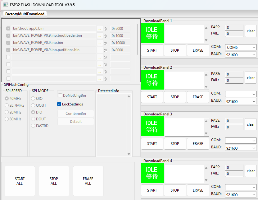
If you encounter any issues, you can reset the Wave Rover to factory settings. Download the Wave Rover Factory firmware and run flash_download_tool_3.9.5.exe. Set the ChipType to ESP32 and choose the WorkMode as Factory.
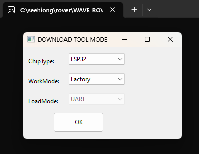
After selecting the COM port, click on the START button.
Troubleshooting
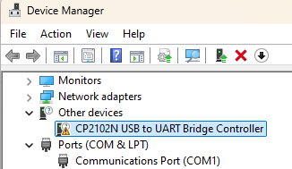
Missing CP2102N USB to UART Bridge Controller
If you encounter this issue, you can download and install the VCP driver from Silicon Labs. After installation, proceed to update the driver in the Windows Device Manager.
No such file or directory (e.g., ArduinoJson.h or Adafruit_GFX.h)
If you are see an error like this:
WAVE_ROVER_demo\WAVE_ROVER_V0.9\WAVE_ROVER_V0.9.ino:1:10: fatal error: ArduinoJson.h: No such file or directory
 #include <ArduinoJson.h>
          ^~~~~~~~~~~~~~~
compilation terminated.
exit status 1
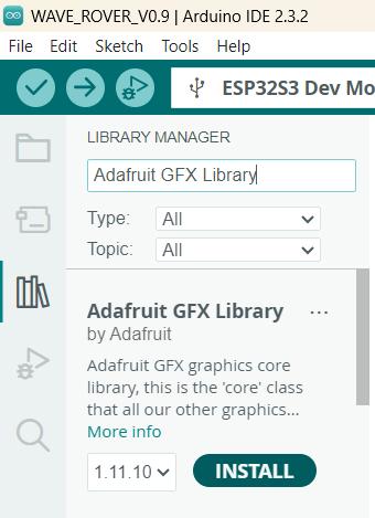
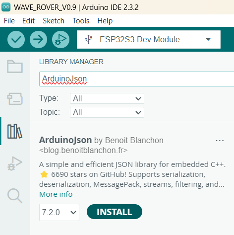
You’ll need to install ArduinoJson from Sketch > Include Library > Manage Libraries:
Similarly, if the compiler reports a missing <Adafruit_GFX.h> file, install Adafruit-GFX via the same method: